 |
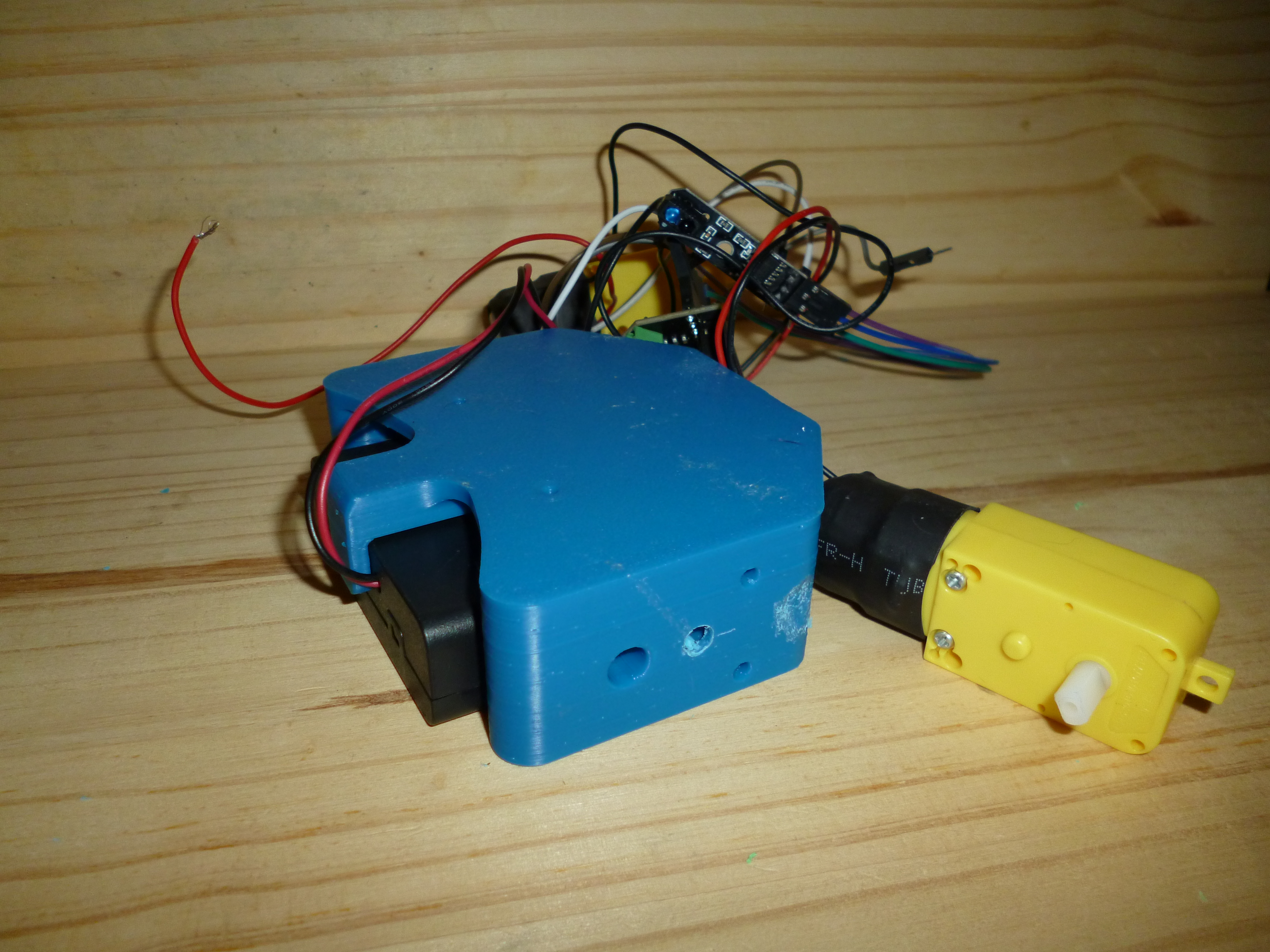
Ignore the mess of wires, I didn't unplug anything from the last build using these guts (from a robotics class back in college). The battery retention part worked as intended, no issues there. The same bulging issue with the threaded inserts appeared, but wouldn't have caused any issues on this part. The biggest issue was with the motor mounting. The model of the motor I have doesn't have the nub on the side opposite the wires that mine does. While I'd like to keep the wires away from the wheels, relaistically I think I'm going to have to add space for the nubs like I did with the drill in this picture. The dent further to the right on the part is for a piece of the motor that is bulging out and also interfered. After I got the motor to mount flush, I realized that I messed up the depth of the counterbore for the screw on the inside and I couldn't screw the motors on anyways. This part will be re-designed with all of this kept in mind.
|
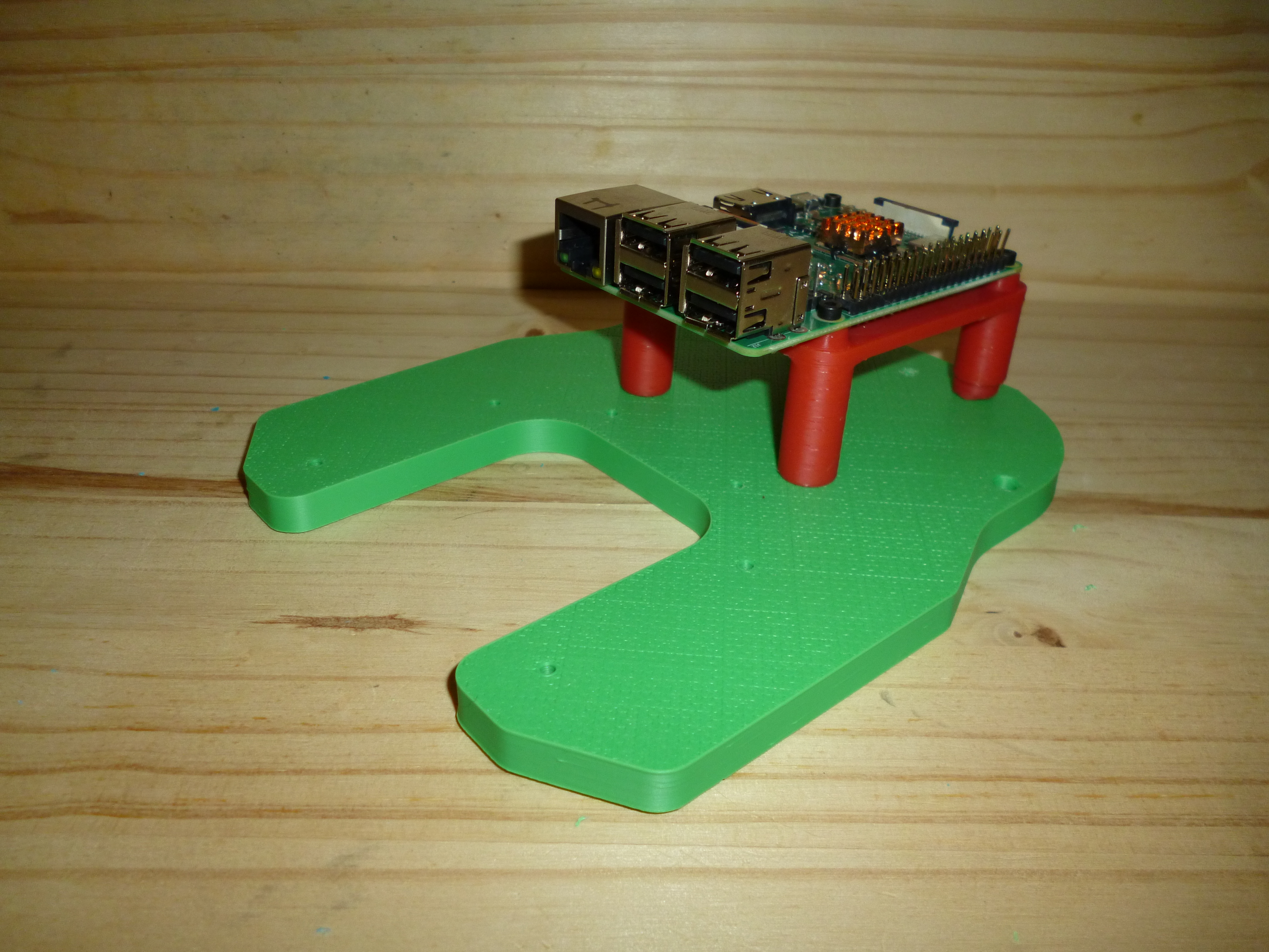 |
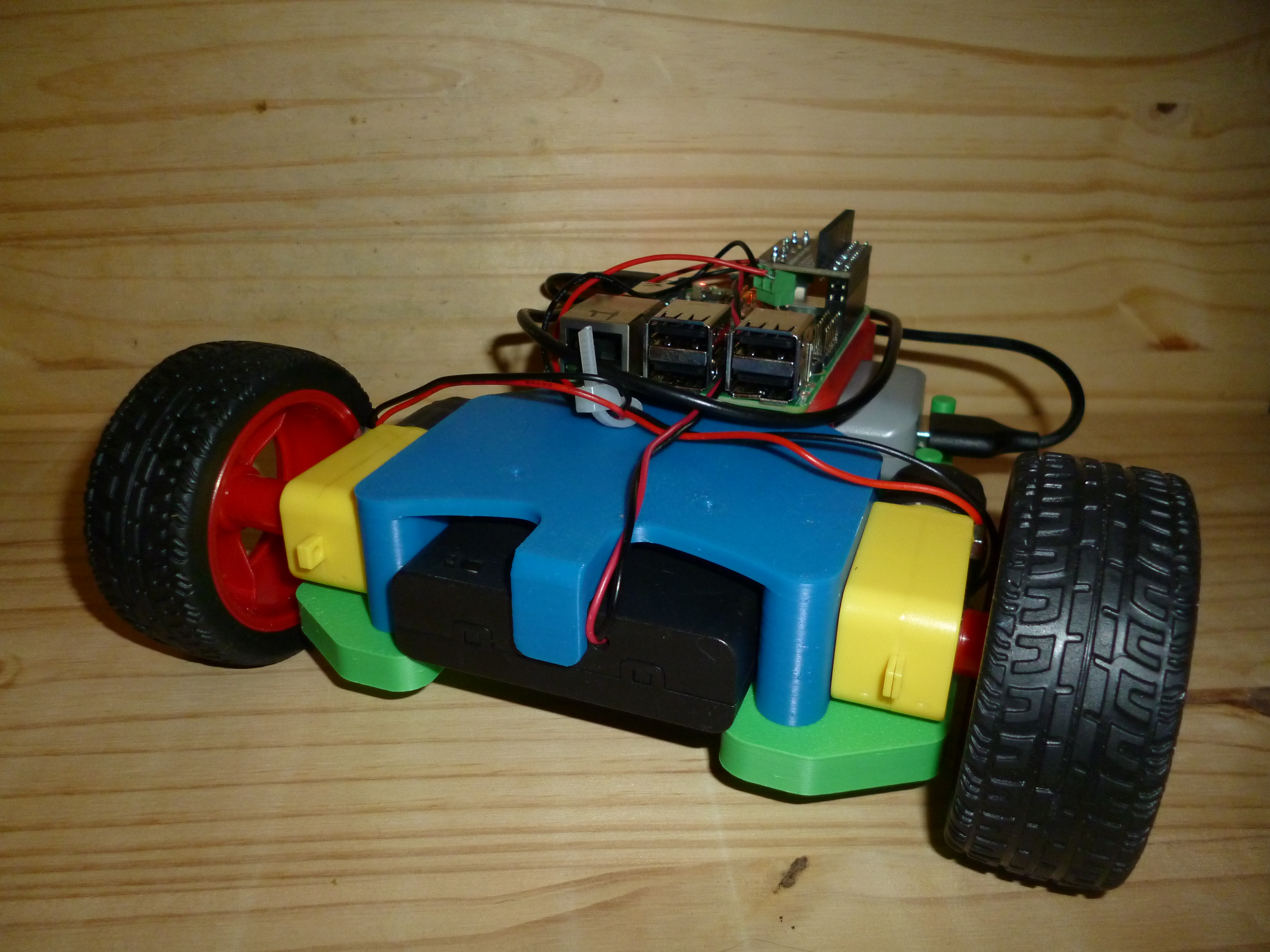
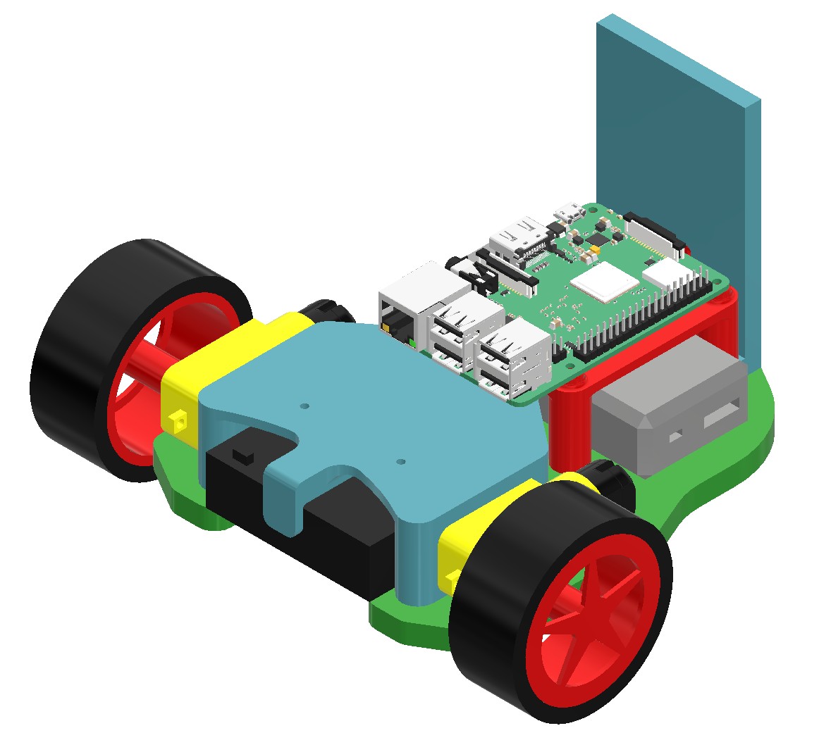
When I printed the first revision of the base and pi mount they had a few problems. The tolerances on the inserts were way off, so the back posts of the pi mount are bulging out. This may get fixed in a later revision, but isn't a big concern right now, and the part that interfaces with it will likely be designed to accomidate how it ended up. The base also had a few issues. Using a M2.5 to retain the battery pack doesn't seem viable once built, so that will need to be replaced. The track ball (not pictured) indent in the back is also perfectly fit to the plastic casing, which means there isn't enough room for the casing to expand and allow the ball to spin.
|